Turning an existing architectural drawing into a usable 3D model is a recurring part of the design process for many architects. Floor plans, elevations and sections often contain much of the information needed. Yet manually reconstructing a building in 3D can still take considerable time.
Advances in AI and automated modelling techniques are changing this workflow. Software is becoming increasingly capable of interpreting information from 2D drawings and using it to build digital 3D models. But how far can this automation really go? And which tasks still require an architect’s knowledge and judgement?
In this article, we explore how converting DWG drawings into 3D works, which steps can be automated and where the limitations of this technology lie. We also discuss what to consider when using an automatically generated model as the starting point for a new design.
What Does Converting DWG to 3D Mean?
A DWG file is a digital drawing format widely used in CAD software, such as AutoCAD. It can contain floor plans, elevations, sections, dimensions and other architectural information. Although a DWG file can also contain 3D geometry, existing buildings are often documented through separate 2D drawings.
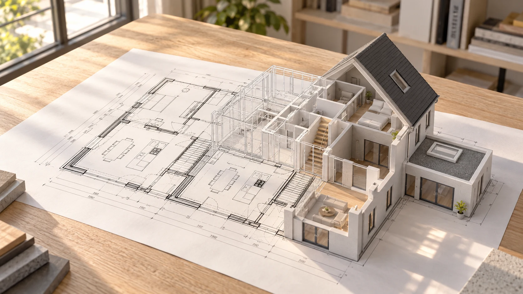
Converting a 2D DWG drawing into a 3D model involves translating this information into a spatial representation of the building. Lines representing a wall on a floor plan, for example, are given a position, thickness and height. Elevations and sections provide additional information about floor heights, window openings and roof shapes.
The result can be a digital model that allows an architect to view and edit the existing building from different perspectives. However, it is important to distinguish between a static 3D visualisation and an editable 3D model. In an editable model, individual elements can be selected and modified, depending on the software used and how the model is structured.
How Does Converting a 2D Drawing into a 3D Model Work?
Converting a 2D architectural drawing into a 3D model begins with analysing the available drawings. A floor plan shows the layout of a building, but does not automatically provide all the information needed to reconstruct its complete three-dimensional structure. Elevations, sections and dimensions are often required as well.
Extracting Architectural Information from Drawings
The first step is identifying and interpreting architectural elements. These include walls, doors, windows, stairs and other parts of the building. When modelling manually, an architect or draughtsperson determines what the lines and symbols represent. Automated software attempts to recognise this information using geometry, drawing layers, symbols and relationships between elements.
From 2D Lines to a Spatial Model
Once the relevant elements have been identified, they can be translated into three-dimensional geometry. A wall, for example, is assigned a height and thickness, while window and door openings are positioned correctly. Additional information from sections and elevations helps determine the building’s spatial proportions.
Which Parts of 3D Modelling Can Be Automated?
Not every step in the 3D modelling process needs to be completed manually. With the help of algorithms, geometric analysis and AI, certain architectural elements can be automatically recognised and converted into 3D geometry. Which elements can actually be automated depends on the software used and the quality of the available drawings.
Walls, Floors and Building Structures
Walls and floors form the basis of many architectural 3D models. Software can analyse parallel lines and closed contours, for example, to identify potential wall structures and floor surfaces. When the correct dimensions and height information are available, these elements can then be converted into three-dimensional geometry.
For simple, consistently drawn floor plans, this can significantly reduce the amount of manual reconstruction work required. However, irregular wall shapes, unclear drawing layers or missing dimensions may still require additional interpretation. Automatic recognition therefore does not mean that every architectural element will be modelled correctly without verification.
Doors, Windows and Openings
Doors and windows are often represented in architectural drawings using recognisable symbols and line combinations. Automated systems can use these patterns to identify openings in walls and determine their positions within the 3D model. Additional information, such as widths and heights, helps refine the geometry.
Accuracy depends heavily on the drawing standards used and the information available. A window clearly indicated on an elevation, for example, is easier to reconstruct than an opening whose height is not documented anywhere. In such cases, manual input or verification may still be necessary.
Building an Editable 3D Base Model
Once sufficient architectural information has been identified, the individual components can be combined into a 3D base model. Depending on the software, walls, floors and other elements can be created as separate objects. This produces a model that can not only be viewed but also modified further.
For architects, editability is particularly important. An automatically generated model can serve as the starting point for exploring design alternatives, adjusting spatial layouts and preparing further design work. Its usability depends not only on visual quality, but also on the structure and accuracy of the model.
What Cannot Easily Be Automated?
Although automation offers increasing possibilities, reconstructing an existing building remains a complex process. A 2D drawing does not always contain all the information required for a complete and accurate 3D model. Drawings may also be outdated, incomplete or inconsistent with one another. This is why assessment by an architect or building specialist remains important.
Missing or Conflicting Information
Complete drawing sets are not always available for existing buildings. Sections may be missing, height dimensions may not be specified, or different drawings may not fully correspond. A floor plan, for example, may show the position of a window without providing information about its exact height or how it connects to the façade.
Automated software cannot always reconstruct missing information reliably. Some systems use assumptions or default values, but these may not reflect the actual building. When important information is missing, an architect must determine which elements require further investigation, measurement or manual completion.
Architectural Details and Complex Geometry
Not every building consists of simple, straight walls and standard openings. Sloping façades, curved structures, changes in level and complex roof shapes can make automated modelling considerably more difficult. Architectural connections and detailing also cannot always be fully derived from the available 2D drawings.
These differences can be particularly important in renovation and conversion projects. Later alterations, for example, are not always reflected in the original drawing documentation. An automatically generated model can provide a useful starting point, but it does not replace a building survey or verification of the actual conditions.
Checking Accuracy and Completeness
A 3D model can look visually convincing without all its dimensions or architectural elements being correct. It is therefore important to compare an automatically generated model with the original drawings. This includes checking wall positions, floor heights, window openings and the connections between different building elements.
The level of verification required depends on the intended use. An initial spatial study may have different accuracy requirements from detailed technical design or construction documentation. Automation can accelerate the preparatory modelling work, but responsibility for assessing and applying the model remains with the professionals involved.
Manual Modelling vs Automated Modelling
When reconstructing an existing building in 3D, architects can choose between manual modelling and a partially or fully automated workflow. Both approaches have their own advantages and limitations. The best choice depends on factors such as the complexity of the building, the available drawings and the intended purpose of the model.
- Time required: Manual modelling involves constructing architectural elements individually. Automation can take over part of this preparatory work.
- Control: With manual modelling, the draughtsperson directly determines how each element is constructed. With automated modelling, checking the result afterwards is important.
- Flexibility: Manual modelling offers considerable freedom when working with complex or unusual building forms. Automation works [REMAINDER OF ORIGINAL TEXT NEEDED].
In practice, these two approaches do not have to be mutually exclusive. An automatically generated 3D base model can provide the starting point, after which an architect adds missing elements, corrects inaccuracies and develops the model further. This allows automation to handle repetitive tasks while the architect retains control over the final result.
This combination can be particularly valuable for renovation, redevelopment and building conversion projects. The existing building often needs to be documented digitally before new design options can be explored. By partially automating the preparatory modelling work, more time can become available for design decisions, spatial quality and technical development.
From DWG to an Editable SketchUp Model
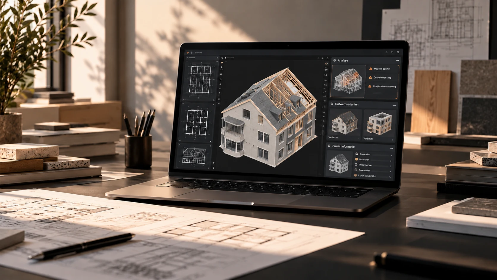
SketchUp is used by many architects to develop buildings in three dimensions and explore design alternatives. An existing DWG drawing can serve as a starting point. With a suitable version of SketchUp, DWG files can be imported, but an imported 2D floor plan is not the same as a fully constructed 3D model.
In a traditional workflow, the imported lines are used to manually model walls, floors, openings and other architectural elements. Automated software can take over parts of this process by recognising information from the original drawings and converting it into three-dimensional geometry.
For further design work, the editability of the result is particularly important. A well-structured SketchUp model allows individual elements to be selected, modified and organised. It is therefore essential to check not only the dimensions and geometry, but also the object structure and how the model has been constructed. This creates a usable foundation for renovation, redevelopment or a new design.
Frequently Asked Questions About DWG to 3D
Can Every DWG Drawing Be Automatically Converted into 3D?
Not every DWG drawing can be converted into a complete 3D model without additional work. The possibilities depend on the quality, completeness and structure of the file. Clear floor plans with consistent drawing layers and dimensions are generally easier to process than incomplete or complex drawings. When important architectural information is missing, manual input or verification may be necessary.
Can PDF Architectural Drawings Also Be Converted into 3D?
PDF architectural drawings can also serve as the basis for a 3D model, but the workflow differs from working with DWG files. A vector PDF generally contains more recognisable line information than a scanned drawing. With scanned drawings, software must first analyse the image to identify architectural elements. Additional checks or preparatory processing may therefore be required before the drawing is suitable for 3D modelling.
Is an Automatically Generated 3D Model Ready to Use?
An automatically generated 3D model can be immediately useful as the basis for an initial design study, but this depends on the quality of the source files and the required level of detail. Further technical development may require additional checks and modifications. Always verify the dimensions, completeness and editability before using the model for design decisions or construction documentation.
What Is the Difference Between a 3D Model and a BIM Model?
A 3D model describes the three-dimensional geometry of a building, while a BIM model can also contain structured information about architectural elements. This may include materials, properties and relationships between components. Not every 3D model is therefore automatically a BIM model. For architects, it is important to determine in advance what information and level of detail are required for the next design stage.
Conclusion: Automation as a Foundation for the Design Process
Converting DWG drawings into 3D does not have to be an entirely manual process. Automated modelling techniques can recognise architectural elements and use them to construct a digital 3D base model. This can simplify part of the preparatory modelling work, provided the available drawings contain sufficiently reliable information.
The greatest value comes when automation and architectural expertise complement one another. Arqetta contributes to this by converting existing 2D architectural drawings into editable 3D models. This allows architects to obtain a digital starting point for their designs more quickly, while control, interpretation and further development remain in the hands of the architect.